Bug #25875
closedDesign VDA Block Diagram issues (refer description)
0%
1. Login as Aqua pro Module Administrator
2. Click on the EWQIMS icon and select EVAV NPD/APQP Platform
3. Click on the Products(Aqua Pro) menu
4. Click on Design VDA and select Architectural/Block Diagram
5. Select Production Item
6. Click on Tool box
7. Select shape and drag to scope box
(add multiple shapes)
8. Click on shape
9. Draw interface line
10. Repeat step 8 & 9
11. Draw interface line all shape/elements
12. Click on refresh icon
13. observe Result
Description
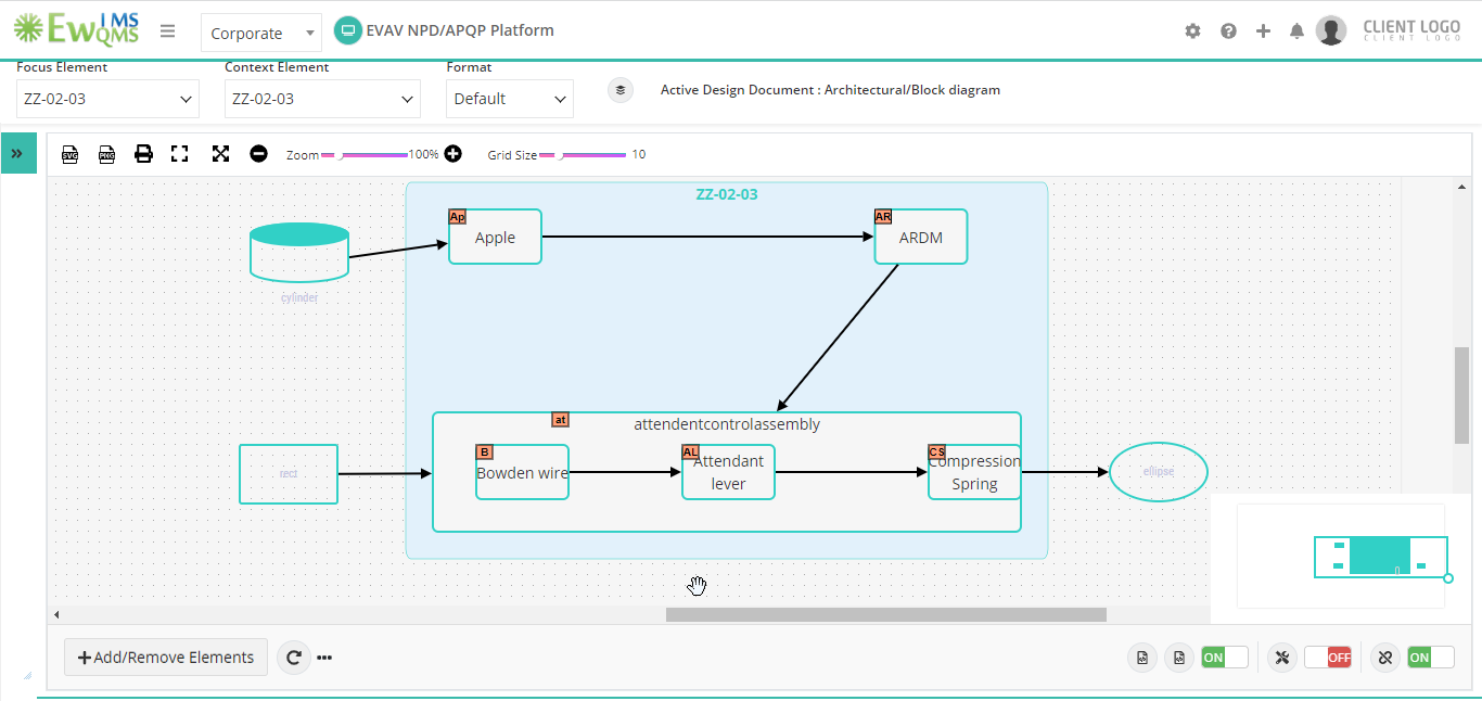
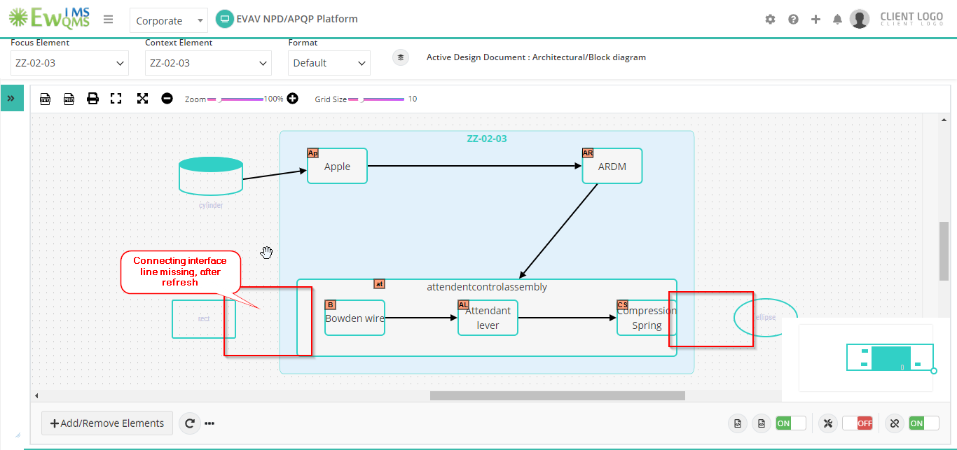
1.0 The system removes all connecting interface lines except for the first connecting interface line when I add multiple shapes and draw connecting interface lines at the same time, after I click the refresh icon. (Refer Screenshot 1.0 & 1.1)
Refer TC: http://saas.omnex.in:81/testlink/linkto.php?tprojectPrefix=EwQIMS&item=testcase&id=EwQIMS-24978
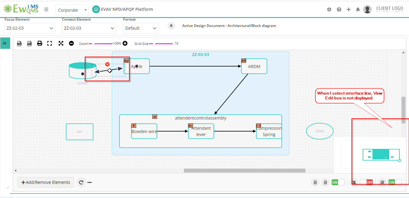
2.0 I select the interface line view edit box not displayed after adding a shape and connecting interface line. (Refer Screenshot 2.0)
Refer TC: http://saas.omnex.in:81/testlink/linkto.php?tprojectPrefix=EwQIMS&item=testcase&id=EwQIMS-24976
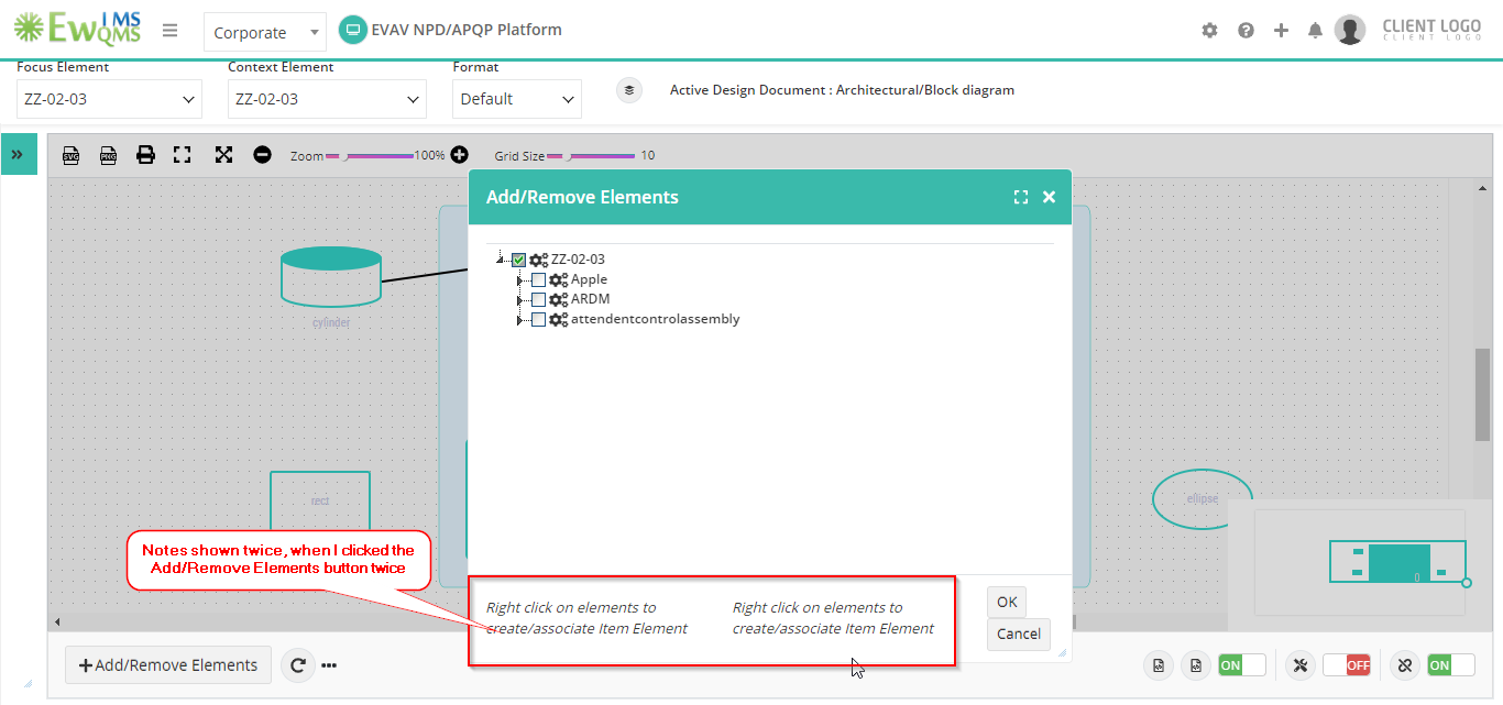
3.0 In the pop up box Notes shown twice, when I clicked the Add/Remove Elements button twice (Refer Screenshot 3.0)
Refer TC: http://saas.omnex.in:81/testlink/linkto.php?tprojectPrefix=EwQIMS&item=testcase&id=EwQIMS-24977
Files